Reinventing debugging on the Numworks
October 19, 2022Hey you, do you want a cheap debugging solution for the Numworks? You’re at the right place. Today we will see how you can get a clean debug port for less than €10.
The current state of the art in Numworks debugging
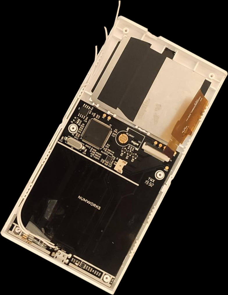
The way debugging was done until now was to solder 3 wires, two to pin 2 and 4 of the debug port, and one to the Micro USB port, for ground. You would then take them out of the case with a hole.
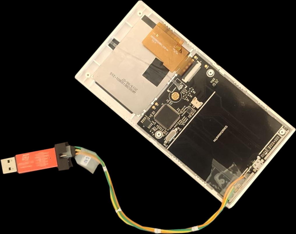
You would then need to buy a separate device, an ST-Link which would cost you almost €50, and plug these wires to it. This solution works, but there are a few downsides, notably:
- This is jenky. As you can see in the previous picture, you would always have cables dangling out of your Numworks, possibly putting strain on the solders which is never a good thing to do
- A separate device (USB<>UART) would be needed to have a serial port
- You wouldn’t be able to debug your Numworks without having an ST-Link on you.
The idea
There is a project called picoprobe which is meant to be used on a Raspberry Pi Pico. This is an official project which is mentioned in the Raspberry Pi Pico’s official documentation. The way they use it is to debug another Raspberry Pi Pico, but we can use it to debug anything that support SWD. This was originally an idea of RapidZapper on the Omega Discord, although he wanted to do it with a smaller clone of the Raspberry Pi Pico.
What you will need
I only had to buy two things, as I already had a soldering iron and solder:
- A Raspberry Pi Pico
- A spool of 26 AWG wire
This costed me less than €10, including shipping.
Modding the calculator
Planning
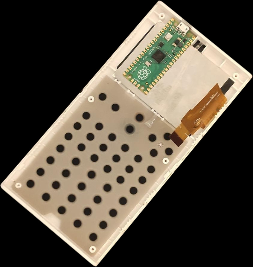
I started by planning where I would put the Pico. The best place that fits without having to put a massive hole in the case is at the back of the screen.
I then marked where I would have to remove support material from the case.
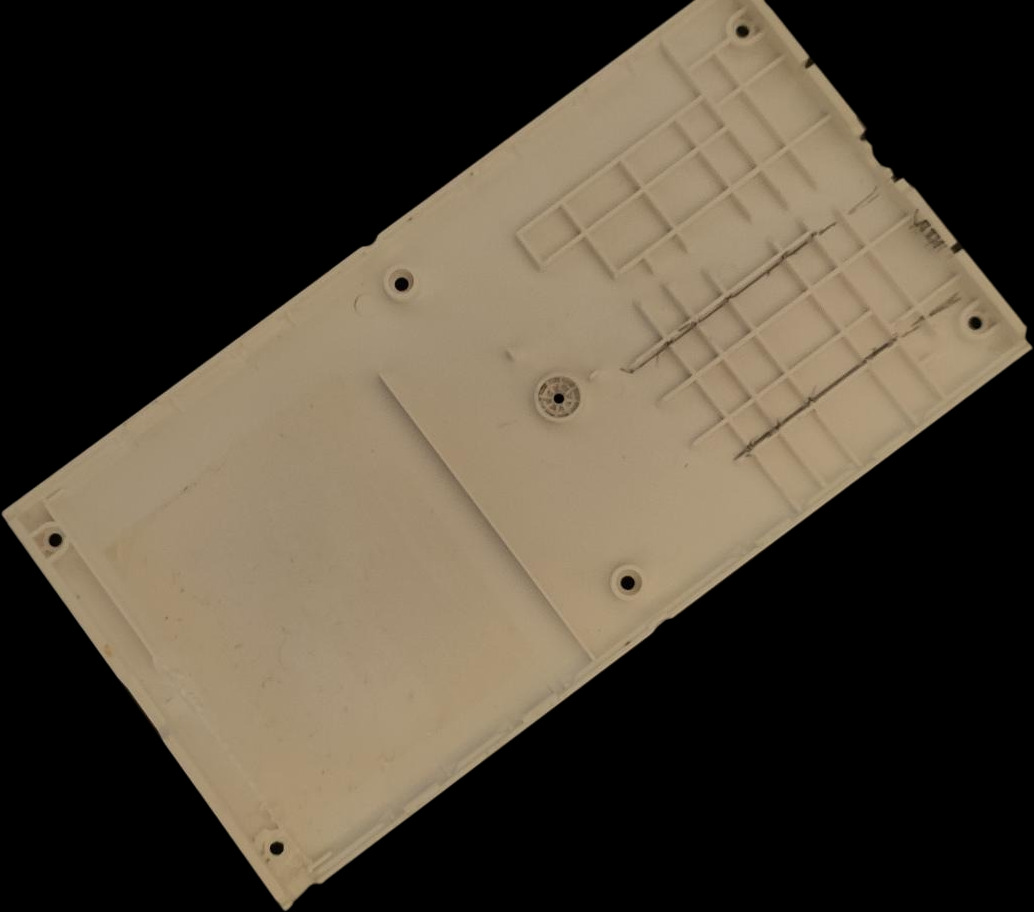
Cutting the case
I then proceeded to remove the plastic from the case, using a pair of pliers and a knife. If you want to do this mod yourself, be sure to cut the full width of the pico from the bottom part of the case. You will only have to cut the width of the Micro-USB port from the top part of the case. You will also have to carve in the bottom part to fit the USB port. If you don’t mind having a giant hole in your calculator, you can also go the easy way and just remove plastic where the Micro-USB port is. You can also cut a hole on the back for the bootsel button of the Raspberry Pi Pico.
Soldering
After doing that, I started soldering. Here is what you have to solder:
- Pico GND -> Find a ground on the motherboard. I used the casing of the Micro USB port.
- Pico GP1 -> Debug pin 2
- Pico GP2 -> Debug pin 4
- Pico GP3 -> RX
- Pico GP4 -> TX
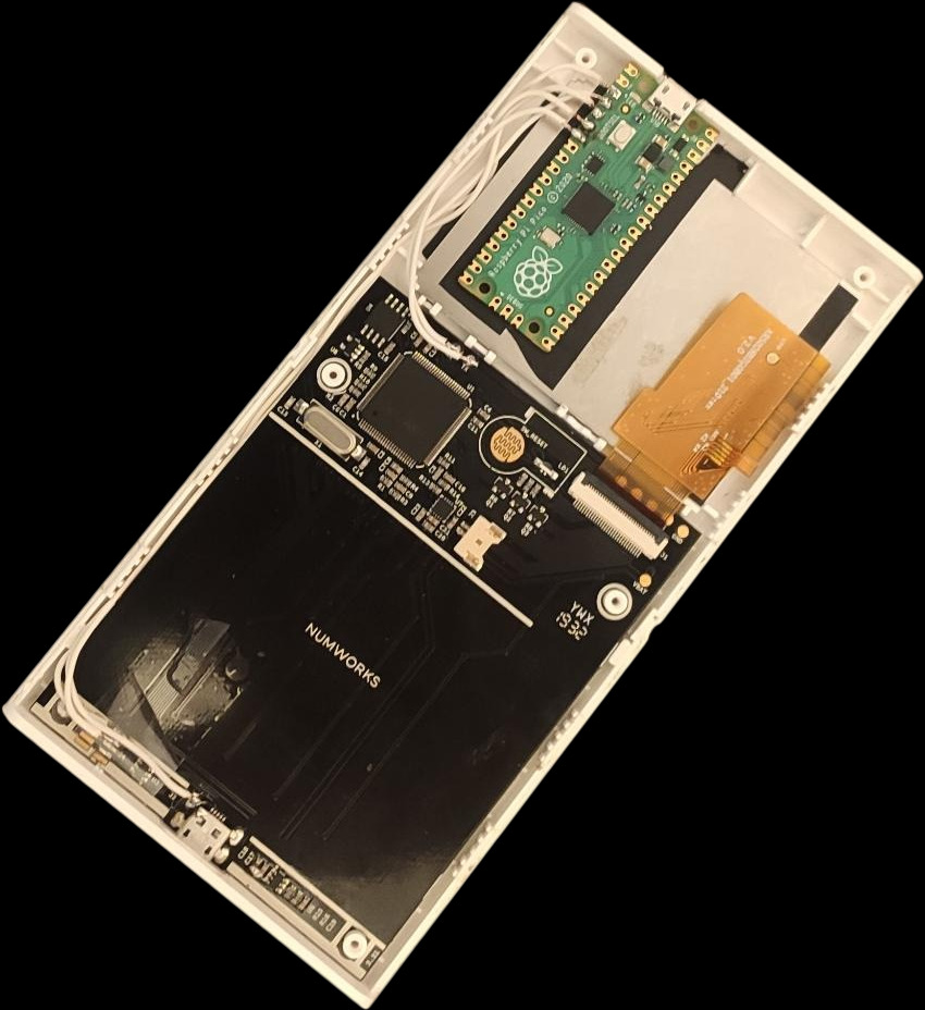
Don’t forget to check if you haven’t shorted anything while soldering. Be sure to isolate the back of the screen with some electrical tape.
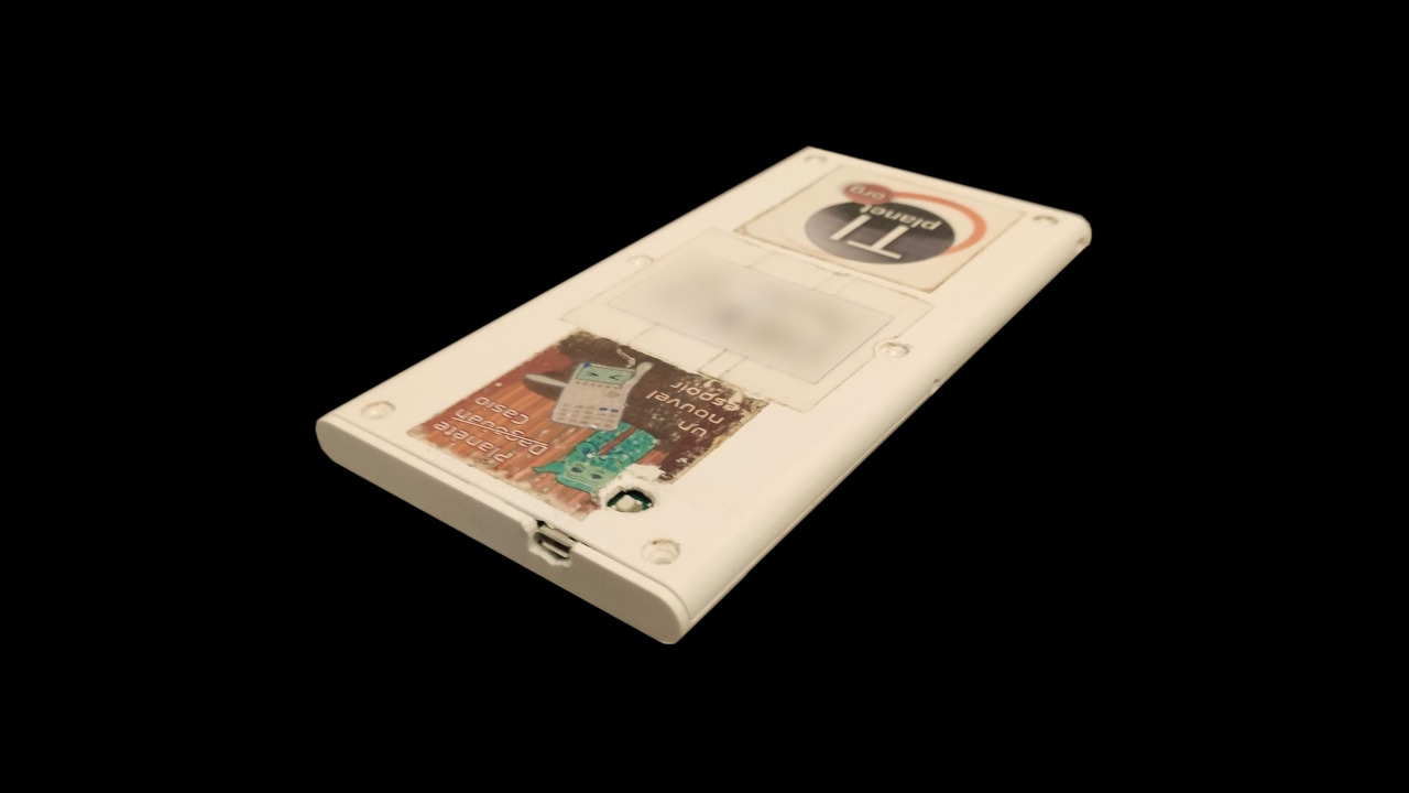
Eventually, after trimming enough plastic from the case, we are able to close it properly. As you can see, I know have a Micro-USB port at the top of the case, to connect the Raspberry Pi Pico to my computer.
Using it
I first downloaded the uf2 binary of picroprobe on the official website. I then pressed the bootsel pin of the Pico and plugged it to my computer. I then installed the firmware by dragging the uf2 file on it.
I also had to install a modified version of OpenOCD that supports using the picoprobe. After that, debugging can be done as usual. The serial port works like any USB to UART adapter.
Exams ?
A question I asked myself is, could I still go to an exam with that thing. The worrying answer is yes, as this doesn’t break the specs of the French exam mode. Why is that worrying you may ask ?
The Raspberry Pi Pico W exists, and it has Wifi and Bluetooth. You could really easily embed it in the calculator without letting the Micro USB port stick out. With a custom firmware and some serial port trickery one could use the Pico to connect to the internet.
This is very hypothetical. I won’t try it, as I don’t have any use for it. And by the way, if you are smart enough to figure that out, to make it work and write the software needed on the Numworks and on the Pico, bro WTF you doing in high school?
Conclusion
This whole process took me almost 3 hours, including carving in the case and soldering. If you want to do it, I would advise you to use smaller wires, like 28 or 30 AWG.
